NDE Associates, Inc. Phased Array UT of CRA Welds
Corrosion resistant alloy (CRA) pipes are used for transport of high sour gas and oil with high percent of hydrogen sulfide. CRA piping can be weld overlay, metallurgically bonded or mechanically lined. Typically, CRA clad pipes are carbon steel with CRA welds (see Figure 1). Carbon steel provides the strength and CRA clad is only for corrosion resistance. CRA materials is mostly Alloy 625. Unlike carbon steel pipes inspected with a single ultrasonic technique and sensitivity, the CRA pipes require inspection not only for weld fill passes but also integrity of the CRA root. Such welds require two seprate sensitivies (a) fill passes and (b) root. Failure of CRA portion of the weld root, that is only 3-5 mm, will expose the sour fluids to carbon steel and can have disastrous effects. Because of this reason, inspection of these pipes should pay special attention to root integrity.
CRA welds are anisotropic and not favorable to conventional shear wave transmission. Inspection of these welds is done by refracted longitudinal waves. Refracted longitudinal waves have a limitation. Inspection is limited to 1/2 vee mode and requires removal of weld cap for 100% coverage. They cannot be used in full vee mode.
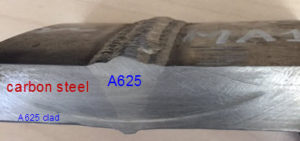
Figure 1. Cross-section of a metallurgically bonded Alloy 625 clad pipe and Alloy 625 weld
CRA WELD CONFIGURATION AND PHASED ARRAY TECHNIQUES
Carbon Steel Pipe with Weld overlay+ CRA weld – 1/2 vee Refracted L wave
Carbon Steel Pipe with weld overlay + carbon steel weld – 1/2 vee Refracted S wave
Solid CRA (duplex SS) – 1/2 vee refracted L-wave
Note – All techniques require removal of weld cap
CONVENTIONAL L-WAVE UT OF CRA WELDS
Refracted dual element longitudinal wave angle beam probes are one of the methods for such inspection. Conventional L-wave probes have a major limitation. They result in scattering or ID roll from weld overlay clad. The ID roll can mask ID indications that are critical for this inspection. Masking of ID indications can be overcome by using phased array probes with focusing on the ID surface (Ref 1).
CALIBRATION OF L-Waves. Side drilled holes and Notches
Another issue is sensitivity calibration of L-waves – side drilled holes or notch
There is a significant difference in reflection between side drilled holes and notches. The signal amplitude from the notch is much smaller than side drilled holes. Figure 7 from from the paper (Ref 2) shows refracted longitudinal waves mode convert when incident on a notch. When incident at 45 degrees on ID notches, refracted longitudinal waves mode convert and lose 16 dB. This drop is significant and results in a large difference in reflection between side drilled holes and ID notches. Figure 7 (d) of the paper shows with sensitivity established on side drilled holes, there is barely any detection of the 1 mm notch.
ID CRACKS CAN BE MISSED IN CRA WELDS
Refracted longitudinal waves when calibrated on side drilled holes as per some engineering codes (Ref 3) have low ID sensitivity and can miss ID cracks. Detection of LOF or ID cracks in root are very critical. Sensitivity should be established on ID notches when inspecting ID connected discontinuities. Reference 2 recommends update sensitivity calibration in engineering codes – to use holes for fill passes and notch for root CRA integrity.
Anmol Birring has been involved with development and application of NDT techniques for Corrosion resistant alloy (CRA) welds since the BP Thunderhorse manifold failures in 2005.
1. Anmol Birring. ” Application of Phased Arrays for Corrosion Resistant Alloy (CRA) Welds“, e-journal of Nondestructive Testing (NDT), ISSN 1435-4934 (NDT.net Journal) Issue 2020-05, May 2020.
2. Anmol Birring, “Selection of Calibration Reflectors for Corrosion Resistant Alloy (CRA) Piping” Materials Evaluation, March 2016, p 361-366
2. DNV-OS-F101, Appendix D, Section B411